Lectures: 2 hrs/week; Practical: 3 hrs/week
AIM: To develop graphic skills in students.
OBJECTIVE:
- To develop in students graphic skill for communication of concepts, ideas and design of engineering products and
- To expose them to existing national standards related to technical drawings.
Concepts and conventions (Not for Examination) ................ 1 hour
Importance of graphics in engineering applications – Use of drafting instruments – BIS conventions and specifications – Size, layout and folding of drawing sheets – Lettering and dimensioning.
UNIT I: PLANE CURVES AND FREE HAND SKETCHING ................ 14 hours
Basic geometrical constructions, curves used in engineering practices: Conics – construction of ellipse, Parabola and hyperbola by eccentricity method – construction of cycloid – construction of involutes of square and circle – Drawing of tangents and normal to the above curves.
Scales: Construction of diagonal and vernier scales.
Visualization concepts and Free hand sketching: Visualization principles - Representation of Three Dimensional objects – Layout of views - Free hand sketching of multiple views from pictorial views of objects.
UNIT II: PROJECTION OF POINTS, LINES AND PLANE SURFACES ................ 14 hours
Orthographic projection – principles – principle planes – First angle projection – Projection of points.
Projection of straight lines (only first angle projections) inclined to both the principal planes – Determination of true lengths and true inclinations by rotating line method and traces
Projection of planes (polygonal and circular surfaces) inclined to both principal planes by rotating object method.
UNIT III: PROJECTION OF SOLIDS ................ 14 hours
Projection of simple solids like prisms, pyramids, cylinder and cone and truncated solids when the axis is inclined to one of the principal plane by rotating object method and auxiliary plane method.
UNIT IV: PROJECTION OF SECTIONED SOLIDS AND DEVELOPMENT OF SURFACES ................ 14 hours
Sectioning of above solids in simple vertical position when the cutting plane is inclined to one of the principal planes and perpendicular to the other – Obtaining true shape of section.
Development of lateral surfaces of simple and sectioned solids – Prisms, pyramids, cylinders and cones – Development of lateral surfaces of solids with cut-outs and holes.
UNIT V: ISOMETRIC AND PERSPECTIVE PROJECTIONS ................ 14 hours
Principles of isometric projection – isometric scale – isometric projections of simple solids and truncated solids – prisms, pyramids, cylinders, cones – combination of two solid objects in simple vertical positions and miscellaneous problems.
Perspective projection of simple solids – prisms, pyramids and cylinders by visual ray method.
COMPUTER AIDED DRAFTING (Demonstration Only) ................ 3 hours
Introduction to drafting packages and demonstration of their use.
TEXT BOOKS:
- Bhatt N.D. and Panchal V.M., “Engineering Drawing” Charotar Publishing House, 50th Edition, 2010.
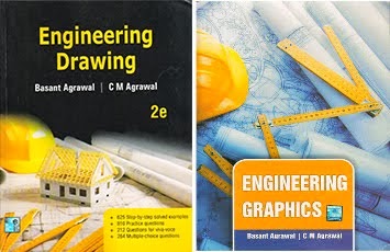
- Basant Agarwal and Agarwal C.M., “Engineering Drawing”, McGraw Hill Education (India) Private Limited, New Delhi, (2013).
REFERENCES:
- Gopalakrishnana K.R., “Engineering Drawing” (Vol. I &II combined), Subhas Stores, Bangalore, 2007.
- Luzzader, Warren.J. and Duff,John M., “Fundamentals of Engineering Drawing with an Introduction to Interactive Computer Graphics for Design and Production", Eastern Economy Edition, Prentice Hall of India Pvt. Ltd, New Delhi, 2005.
- Shah M.B., and Rana B.C., “Engineering Drawing”, Pearson, 2nd Edition, 2009.
- Venugopal K. and Prabhu Raja V., “Engineering Graphics”, New Age International (P) Limited, 2008.
- Natrajan K.V., “A text book of Engineering Graphics”, Dhanalakshmi Publishers, Chennai, 2009.
Publication of Bureau of Indian Standards:
- IS 10711 – 2001: Technical products Documentation – Size and lay out of drawing sheets.
- IS 9609 (Parts 0 & 1) – 2001: Technical products Documentation – Lettering.
- IS 10714 (Part 20) – 2001 & SP 46 – 2003: Lines for technical drawings.
- IS 11669 – 1986 & SP 46 – 2003: Dimensioning of Technical Drawings.
- IS 15021 (Parts 1 to 4) – 2001: Technical drawings – Projection Methods.
Special points applicable to University Examinations on Engineering Graphics:
- There will be five questions, each of either or type covering all units of the syllabus.
- All questions will carry equal marks of 20 each making a total of 100.
- The answer paper shall consist of drawing sheets of A3 size only. The students will be permitted to use appropriate scale to fit solution within A3 size.
- The examination will be conducted in appropriate sessions on the same day